CMM, height gauge or optical comparator: choosing the check for each feature
October 14, 2026
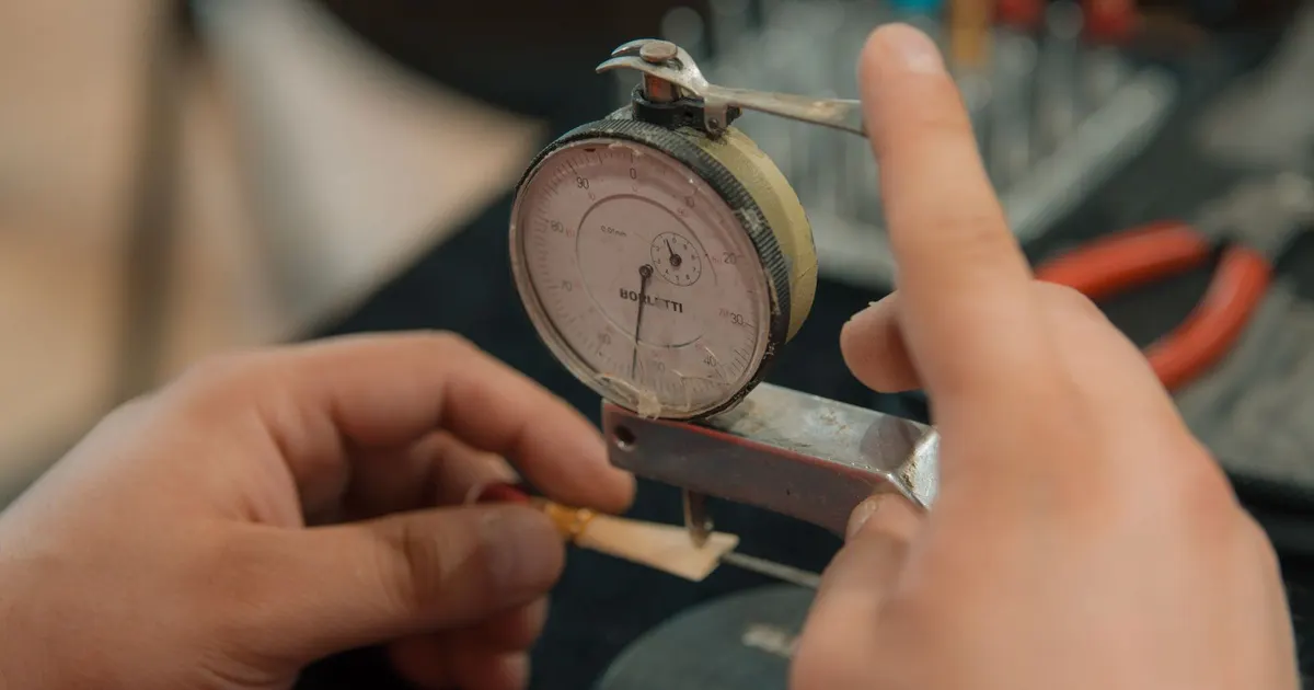
Pick the instrument by the feature you need to check and the tolerance on it, not by habit or price. A CMM measures position and profile in three dimensions. A height gauge on a surface plate measures heights and steps quickly. An optical comparator shows a silhouette. Each has features it cannot measure well.
What each instrument does
Coordinate measuring machine (CMM). A touch probe, or sometimes a scanning or optical head, moves to points on the part and records coordinates. Software builds features from those points, then reports size, position, flatness, profile and the relationships between features. It handles GD&T callouts that no hand tool can check. The cost is programming time and a temperature-controlled room, and the part must be held steady during the measurement.
Height gauge on a surface plate. The part sits on a granite plate. A column with a probe slides up and down and reads the height of a feature above the plate. A digital height gauge reads to a few thousandths of a millimetre in good hands. It is fast and cheap, and it works well for steps, hole heights and simple positions from a datum face.
Optical comparator or profile projector. A light shines past the part and casts a magnified shadow on a screen or camera. The operator compares the shadow with an overlay or reads the edge position on the screen. It measures profile, thread form, small radii and parts that are too flexible to touch. It sees only the outline, not depth.
Matching the tool to the feature
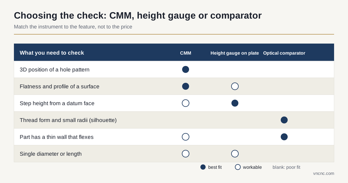
The diagram shows a typical match. In table form, with typical notes:
| Feature | First choice | Why |
|---|---|---|
| Position of a hole pattern | CMM | Needs coordinates from a datum |
| Flatness, profile of a surface | CMM | Many points, software fit |
| Step height from a datum face | Height gauge | Fast and direct |
| Single outside diameter | Micrometer | Faster and as accurate |
| Bore diameter | Bore gauge or air gauge | Direct reading on the surface |
| Thread form, small radius | Optical comparator | Silhouette shows the profile |
| Thin or soft part | Optical comparator | No contact force |
| Thread fit | Go and no-go thread gauge | Checks function, not form |
Real parts need several tools. One report often combines a CMM for position, a micrometer for diameters, a thread gauge for threads and a roughness tester for surface finish. The report should name the instrument for each line.
Uncertainty and the tolerance
Every measurement has an uncertainty. A common rule of thumb is that the tool uncertainty should be about one tenth of the tolerance, and never worse than one quarter. If a hole is toleranced at plus or minus 0.01 mm, the tool should resolve about 0.001 to 0.002 mm. A caliper that reads to 0.02 mm cannot judge that hole at all.
The reverse is also true. A loose tolerance does not justify a CMM report. A bracket with plus or minus 0.2 mm on every dimension is fine with a caliper and a gauge. Asking for a full CMM report adds cost and no information.
The rule of thumb leads to three practical points:
- Know the tolerance on the dimension that decides function. If you do not mark it, the shop treats all dimensions alike.
- Ask what the instrument and its uncertainty are for the critical dimensions.
- Check temperature. Steel grows about 0.012 mm per metre for each degree Celsius. For small parts the effect is minor, for long parts and tight tolerances it matters. Aluminium grows about twice as much.
What to write on the drawing
A drawing that marks critical dimensions with a clear symbol lets the shop plan the check. A few options:
- Balloon every dimension so each report line maps to the drawing.
- Mark critical characteristics with a symbol or a note such as “CC”, defined in a general note.
- State the datum scheme with GD&T if the function depends on it. See the GD&T guide for the basics.
- Say which characteristics need a measured value in the report and which only need pass or fail.
Without this, a shop will choose the cheapest tool that proves compliance. That is a fair choice, and it may not be the one you wanted.
The report you can ask for
Three levels of report are common:
| Level | Content | Typical use |
|---|---|---|
| Pass or fail | Signed statement that parts meet the drawing | Low-risk parts, loose tolerances |
| Measured values | Actual value per dimension for a sample | Most commercial parts |
| Full dimensional report | Every ballooned dimension, instrument, uncertainty | First article, critical parts |
A report that says pass on every line with no values tells you little. Real measurements scatter around the nominal, and seeing the scatter tells you how much margin the process has. The first article guide describes what belongs in the report and how to read it.
Sample plans
You rarely need every piece measured on every dimension. A typical plan, to agree in the RFQ:
- First article: full dimensional report on 1 to 3 pieces.
- During the run: critical dimensions on a stated frequency, for example every 10th to 25th piece.
- Final lot: a sample drawn by a published plan such as ISO 2859-1, with the sample size and acceptance rule written down.
- Safety or high value parts: every piece on the critical dimensions.
State the plan, and the shop prices it. A tighter plan costs more because it takes more measurement time and more programming.
Where checks go wrong
Four faults come up often:
- The wrong tool for the tolerance. A caliper used on a plus or minus 0.01 mm feature.
- The part is measured before it settles. A part straight from the machine is warm. Its size reads wrong until it cools.
- The datum is not the one on the drawing. The CMM program sets up on a convenient face rather than the datum the drawing names.
- Burrs and chips on the part or the plate. A burr under a part tilts it and shifts every height.
All four come from a procedure that was not written down. A short inspection plan that names the datum, the tool and the sample size avoids them.
How we handle inspection
Inspection sits before packing and the engineer on the order owns it. We agree the tool and the sample plan with the shop before the run, and the weekly update reports the inspection results so far. Measured values and the instrument used are part of what we send when you ask for them in the RFQ. See how quality works on an order for the gates.
Other options worth knowing
Three more tools appear in reports:
- Vision measuring machines. A camera and software measure small 2D features without touching them. They suit thin, soft or tiny parts such as stampings and small turned components.
- Air gauges. Air flow through a nozzle measures a bore very precisely and quickly. They suit high-volume checks of bore size.
- Laser scanners. They capture a surface as a cloud of points and compare it with a model. Useful for free-form shapes, less so for a plain turned part with a few diameters.
Use the simplest tool that is accurate enough. The aim is a report you can trust, not the most impressive instrument.
Next step
Before you release the drawing, check:
- Are the critical dimensions marked and ballooned?
- Is each tolerance wide enough for the tool that will check it?
- Is the datum scheme clear, with GD&T where position matters?
- Have you said whether you need pass or fail, measured values or a full report?
- Have you stated the sample plan for the first article and for the run?
Then send the drawing and we will confirm the checks and the report on the quote.
Questions we get on this
Do I need a CMM report on every part?
No. A CMM report on the first article and on a sample plan is normal. A report on every piece adds cost and is only worth it for safety or high-value parts. State the plan you want in the RFQ.
Is a CMM more accurate than a micrometer?
For a single diameter a good micrometer is as accurate and much faster. A CMM wins on position, profile and relationships between features, which a micrometer cannot measure.
What is a CMM report worth if the tolerance is loose?
Little. If the tolerance is wide compared with the tool uncertainty, a caliper check is enough and a CMM report only adds cost. Match the tool to the tolerance.
Have a part like this?
Send the drawing. We shortlist the shop we place it with that run the process and material, and answer within 24 business hours.
Send a drawing